Please note that this website uses cookies. By clicking “Agree” or continuing to browse, you agree to the use of cookies. You can revoke your consent at any time by changing your web browser settings. More about cookies – Cookie Policy.
Go back
Transmissive Optical Components for >100 kW CW Laser Systems
Transmissive Optical Components for >100 kW CW Laser Systems
Fiber end caps, <1 ppm absorption AR coated optics
By Marius Gželka, 2019
High-power continuous-wave laser systems
Since the invention of the first laser in 1960, the constant development and expansion of laser technology have led to the production of the modern-day versions of high-power continuous-wave (CW) laser systems that are now being used in various industries (such as material processing, heavy industry, etc.). As they help to increase the growth of companies and open up new opportunities, they are becoming one of the key components of these sectors.
In one of the most common applications – the processing of materials (including cutting, drilling, and welding) – laser systems bring many benefits compared with alternatives, such as flexibility (enabled by a wide choice of parameters), high speed, precision processes, automation feasibility and low maintenance requirements [1].
Nowadays, industrial laser systems are reaching continuous-wave powers at hundreds of kilowatts level [2]. Manufacturers of different types of lasers (fiber, solid-state, CO2, etc.) are involved in power-scaling competition, and while that is one of the goals that unite them, there are also some shared unwanted effects that they all face in developing such systems.
Optical components for high-power CW systems
Optical components are the most critical part of high-power CW laser systems which, in most cases, are a limiting factor for the output power. In solid state lasers, they are used in almost every stage (intra-cavity, beam delivery optics, etc.), while for fiber lasers they are mostly used for output and beam delivery purposes. One of the most important components of high-power fiber laser systems is end caps. End caps must withstand the highest power fluences (the purpose of the end cap is an initial reduction of the power density) while keeping the appropriate beam quality; thus, special attention needs to be paid to this optical component [3].
Since high-power CW laser systems enable extremely high power fluences, when the light passes through the optical component part of the energy is absorbed and converted into heat, which can have a number of detrimental side effects. One of these negative effects is the heating of the remaining parts of the system (holders, electronic schemes, etc.) which poses a threat to the appropriate performance of the laser system. Another side effect is thermal lensing, it causes a distortion of the beam quality and the beam focusing, which could lead to a potential system failure (damage of further optical components) or introduce inaccuracies into the application [4]. The worst case scenario is laser-induced damage to the optical component [5]. Damaged components can no longer be used, which means that the maintenance and cost of the laser system increase with each low LIDT component. It also results in major disruptions to the further development of the system. Since thermal absorption is the dominant mechanism in a continuous-wave regime [5], absorption of the optical component must be reduced to a minimum level. These issues present a real challenge for the manufacturers of optical components, whose main task is to enable the further development of such laser systems.
Challenges of enabling higher powers
In order to enable the further power scaling of laser systems, constant attention must be paid to the development of top-notch optical components. The most important milestones in the manufacturing process of optical components have to be understood. Once they have been identified, the processes must be strictly controlled and display repeatability. There are several stages of the manufacturing process, and each of them can be a limiting factor for the entire optical system.
Selection of appropriate materials
The first step in the optical component manufacturing process is the selection of an appropriate material. The most popular materials used for laser applications in the UV-NIR range are fused silica (FS) and borosilicate (BK7) glasses due to their optical and mechanical properties. Depending on the application, the appropriate inclusion class and homogeneity grade has to be chosen. When it comes to high CW powers, especially in the NIR range, everything that could cause absorption has to be considered. In this case, special materials of the highest quality have to be used. Such high purity materials (Corning 7979, Suprasil 300, etc.) have low metal impurities (<1 ppm) and a low-oxygen hydrogen (-OH) concentration (<1 ppm) that results in no absorption bands from the visible to the NIR spectral region (Figure 1). Due to a more complex production process, the price of such materials is generally higher, but since it is very important to eliminate all possible absorption sources, the right materials for high-power laser systems have to be selected.

Figure 1. Transmission spectra of uncoated fused silica materials.
High quality material processing
Even when the right material has been selected, detrimental effects are not eliminated if improper material processing techniques are used. The primary optical component fabrication can be separated into a few main stages: shaping, grinding and polishing of the substrate. Each stage contributes to the quality of the finished substrate: it generates stress and strain on the optical surface and contaminates the substrate with polishing residuals [6]. These processing results increase the absorption and scattering, which results in lower LIDT values and a shorter lifetime of the optical component. In order to minimize these effects, it is very important to understand the correlation between the process and element quality and to constantly make efforts to improve them. When an extremely high quality of the substrate is required, special polishing methods (such as MRF) are used after the conventional polishing. With such manufacturing stages, super-polished substrates with <1Å surface roughness and minimal subsurface defects (SSD) are produced.
Special surface treatment methods for subsurface defects removal
Even when high-end polishing methods are used, subsurface defects (the weakest links of an optical component) cannot be completely eliminated. For high power fluences, when an optical component of perfect quality is required, finishing surface treatment processes should be considered. Contactless methods such as plasma etching help to reduce the SSD to the minimal level and increase the LIDT values of the optical components (Figure 2) [7]. However, a deep understanding and numerous experiments are required in order to select the optimal parameters (etched layer thickness, etching speed, etc.) for each case. The etching procedure is performed in the same coating machine vacuum chamber just before the coating process, which helps to prevent any contamination.

Figure 2. Damage morphology comparison of etched and non-etched substrates.
Selection of appropriate coating materials and coating technology
Coating materials have different properties and, depending on the customer’s laser parameters, a perfect fit has to be selected. In some cases, even when all the parameters of the laser are locked and only the pulse duration changes (ns compared to fs), it is necessary to use different materials due to different damage mechanisms [5]. For high-power CW laser systems, absorption is the key factor of the optical component; thus, coating materials that have the lowest possible absorption and special methods for absorption reduction have to be used. Nonetheless, it is not only the coating materials that have an impact on the optical performance and LIDT values, but also the coating design (number, the thickness of the layers, sublayers, etc.), which has to be customised according to each customer’s needs. The coating technology also strongly influences the quality of the final product. Important properties, such as the optical performance, coating density, durability, sensitivity to humidity, aging effects, etc., depend on the selected technology. For the production of high quality optical components, Ion Beam Sputtering or Magnetron Sputtering (Figure 3) coating technologies are usually used.
Quantities per coating run:
- 1790 pcs. of Ø12.7 mm
- 518 pcs. of Ø25.4 mm
- 126 pcs. of Ø50.8 mm
- 42 pcs. of Ø76.2 mm

Figure 3. Altechna’s Magnetron Sputtering coating technology.
Altechna’s solutions for the highest powers
After a thorough analysis of each production stage for optical components, and by working in collaboration with high-power laser manufacturers, Altechna has developed top-notch optical components for high-power CW laser manufacturers and integrators while ensuring perfect repeatability.
Low absorption and reflectance AR coatings
One of Altechna’s latest achievements is extra low absorption (<1 ppm) (Figure 5) and reflectivity (<0.1%) (Figure 4) anti-reflective coatings for high-power CW laser applications. The coatings are made with Magnetron Sputtering coating technology, in addition to using special methods for minimising absorption.

Figure 4. Reflectance spectrum of AR coated (1080 nm) IRFS substrate.
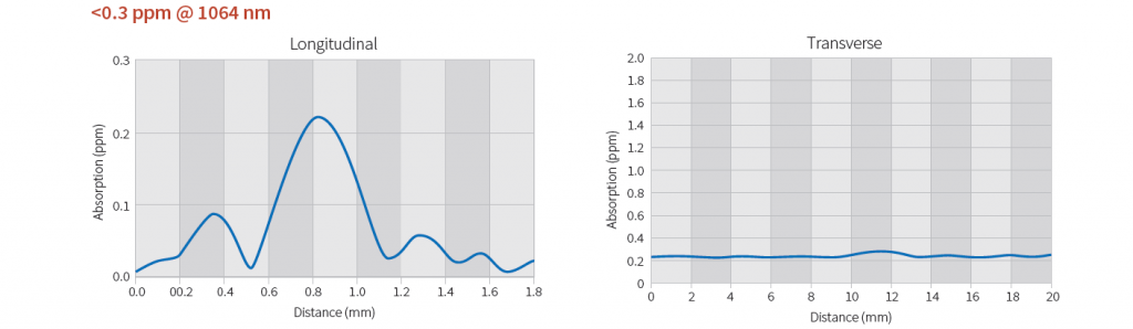
Figure 5. Surface absorption measurement graphs of AR coated IRFS substrate.
End caps for kW fiber lasers
Due to the small diameter of the fiber extremely high power densities can cause scorching and damage of the end-face. These detrimental effects can be avoided by using a fiber end cap, which helps to extend the range of applications to higher laser powers [3]. The beam divergence within the spliced end cap leads to significantly lower power densities at the glass/air interface; nevertheless, when high-power fiber lasers are used, the power densities are still sufficient to initiate strong heating and damage of the end cap which causes a lot of problems for high-power fiber laser manufacturers.
Altechna provides a solution by offering custom end caps with extremely low absorption (Figure 5), high LIDT values (Figure 6), tight mechanical tolerances and flawless optical performance, resulting in a perfect beam quality. Every specification is evaluated and confirmed in our metrology laboratory.
Main specifications:
- Material: Fused Silica (C7979, Suprasil 300 and similar)
- Surface flatness, PV: λ/10 @ 632.8 nm
- Surface quality: 10 – 5, S-D
- Parallelism: <10 arcsec
- Concentricity tolerance: <0.05 mm
- Perpendicularity tolerance: <0.05 mm
- Angle tolerance: <0.1°
- AR coatings: R <0.1%
- Absorption: <1 ppm
Protective windows for high-power lasers
Protective windows are found on the front part of every laser cutting and welding system, and these are crucial for ensuring the reliable and uninterrupted operation of the laser systems. They are designed to be used as a safeguard for the more expensive optics and are placed as the last optics before the work piece. Our experience has led us to achieve spectacular results with high-power systems (Figure 6).
Main Specifications:
- Material: Fused Silica (C7980, C7979 and similar)
- Transmitted wavefront distortion, PV: λ/10 @ 632.8 nm
- Surface quality: 10 – 5, S-D
- Parallelism: <10 arcsec
- AR Coatings: R <0.1%
- Absorption: <1 ppm
LIDT measurements of Altechna’s AR coated optical components
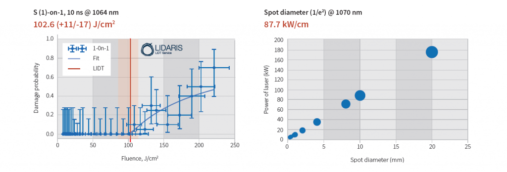
Figure 6. Pulsed and CW regime LIDT measurement graphs.
Custom transmissive optical components
We are able to offer solutions for any custom transmissive optical components (windows, lenses, prisms, etc.) used for high-power CW laser systems. Feel free to contact our professional team and we will provide you with our best support: [email protected].
References
[1] Hull R., Jagadish C., Osgood, Jr. R.M., Parisi J., Wang Z., Warlimont H. / Laser Processing of Materials, Springer, Materials Science 139 (2010)
[2] Shcherbakov, E., Fomin, V., Abramov, A., Ferin, A., Mochalov, D., & Gapontsev, V. P. / Industrial Grade 100 kW Power CW Fiber Laser, Advanced Solid-State Lasers Congress (2013)
[3] Knigge A., Knothe C., Oechsner U., Federau G. / Fibers with end caps, Physics’ Best, pp. 2-5 (2017)
[4] Bogan, C., Kwee, P., Hild, S., Huttner, S. H., & Willke, B. / Novel technique for thermal lens measurement in commonly used optical components, Optics Express, 23(12) (2015)
[5] Yu, J., Xiang, X., He, S., Yuan, X., Zheng, W., Lü, H., & Zu, X. / Laser-Induced Damage Initiation and Growth of Optical Materials, Advances in Condensed Matter Physics, 1–10 (2014)
[6] Pfiffer, M., Longuet, J.-L., Labrugère, C., Fargin, E., Bousquet, B., Dussauze, M., Néauport, J. / Characterization of the Polishing-Induced Contamination of Fused Silica Optics, Journal of the American Ceramic Society, 100(1), 96–107 (2016)
[7] Juškevičius, K., Buzelis, R., Abromavičius, G., Samuilovas, R., Abbas, S., Belosludtsev, Kičas, S. / Argon plasma etching of fused silica substrates for manufacturing high laser damage resistance optical interference coatings, Optical Materials Express, 7(10), 3598 (2017)