Please note that this website uses cookies. By clicking “Agree” or continuing to browse, you agree to the use of cookies. You can revoke your consent at any time by changing your web browser settings. More about cookies – Cookie Policy.
Go back
Quick Guide to the Selection of CW Laser Optics
Quick Guide to the Selection of CW Laser Optics
By Laurynas Lukoševičius, Ph.D., 2023
Market trends in CW laser systems
The maximum power of the continuous wave (CW) lasers on the market has been continuously growing, and has increased by almost a thousand times in just over a decade. Additionally, the beams of CW laser systems have been reduced in size due to the capability to use compact fiber lasers operating at kilowatt laser powers, without the need for additional sophisticated cooling.
A major technological advance like this has created new production technology possibilities and permanently altered the industrial production techniques including cutting, drilling, welding, rust-cleaning, surface hardening, and other technologies employed in the Automotive, Aerospace, and Materials fields.
Most of the manufacturers and users of such lasers are currently dealing with new challenges related to laser damage resistance and stability of the optical component, particularly in laser systems that use optical components with interference coatings. When high laser powers or small laser beams are employed, such laser system components and coatings degrade over time, losing their optical properties and eventually being damaged.
Temperature-induced defects are primarily accountable for these adverse effects on CW systems. Heating may also result in thermal lensing and the focal shift phenomena, which reduces the system’s precision. Furthermore, to avoid absorption-related issues, active cooling methods that take up more space, are less cost-effective, and that make the system more complicated, are necessary.
There is an alternative solution that could be employed – the internal heating can be eliminated by using low-loss optical components. To address the above-mentioned issues and to significantly improve the optical component resistance to CW laser radiation, a thorough understanding of the behavior of optical components under high CW laser powers, as well as proper testing methods, are required.
Furthermore, the rapidly growing irradiation fluences of CW laser systems need up-to-date optical components that can withstand absorption-caused deviations in the beam quality and focusing, as well as laser-induced damage. The vital aspects to consider when selecting an optical component for your high-power CW laser system will be outlined in the following sections.
Laser damage resistance in CW mode
As multiple studies have already suggested, thermal melting of the optical component is one of the main reasons for laser irradiation damage [1]. Therefore, laser damage resistance is one of the key elements of the optical component. Even though some optics have similar spectral capabilities, they might perform differently in the same laser system due to different properties of the optical component [2]. This is also the case in continuous wavelength applications.
To have a trustworthy laser system and a smooth optics integration procedure before choosing your optics, you must consider the resistance of the optics to laser damage radiation. As part of this evaluation, specific laser parameters such as the wavelength, average beam power (P), beam diameter (deff), power intensity distribution within the beam (Gaussian, Flat Top, or other), and the angle of incidence (AOI) must be considered, as is suggested by Equation 1 for calculating the linear power density (LPD) and power density (I).
Unlike standard pulsed laser applications, the LPD or I value is usually used to define the optical component laser-induced damage threshold (LIDT) in the case of CW or quasi-CW (q-CW) laser radiation. Most often, it is not just the power density, but also the total power that has an effect on this component in real-life conditions.
Some defects caused by laser radiation may be fully destructive to the optical component (catastrophic), while others may only lead to surface deviations; therefore, multiple types of resistance levels could be important for a variety of individual applications. With shorter wavelengths, lower laser powers are required to damage the component. Catastrophic breakdowns are not that common at the power levels currently available in the CW laser market unless high-power laser systems with focused laser beams are employed [3].

Equation 1. a) Linear power density; b) Power density in relation to the laser beam properties.
Beam quality and stability in CW applications: thermal effects, absorption, and focal shift
Another property important for the application of the CW and q-CW laser optics is overheating, which is caused by absorption and leads to undesirable beam deviations or distortions created by the thermal lensing effect (Figure 1). In most cases, the temperature change in the optical
component is linearly proportional to the laser irradiation power.
The influence of the change in surface temperature on the thermal lens formation is described in Figure 1. In the case of a few hundred watts of power, the ~10 ppm absorption levels could be negligible for the application; however, laser systems with demanding laser beam quality requirements may need optics with few ppm or even sub-ppm absorptions at the NIR range.
With the purpose of demonstrating the negative effects caused by temperature, optics with a higher absorption level of 10 ppm have been chosen to demonstrate a clear change in the laser beam distortions, which may change a couple of times in PV with a higher surface temperature difference (ΔT=11˚C).
A single ppm absorption requirement is quite common in advanced spectroscopy CW lasers that need to be very stable, or for very precise lasers in fine structure processing in the NIR range.
Despite the variety of laser parameters and applications, Altechna can provide an optics solution specifically for your CW application.
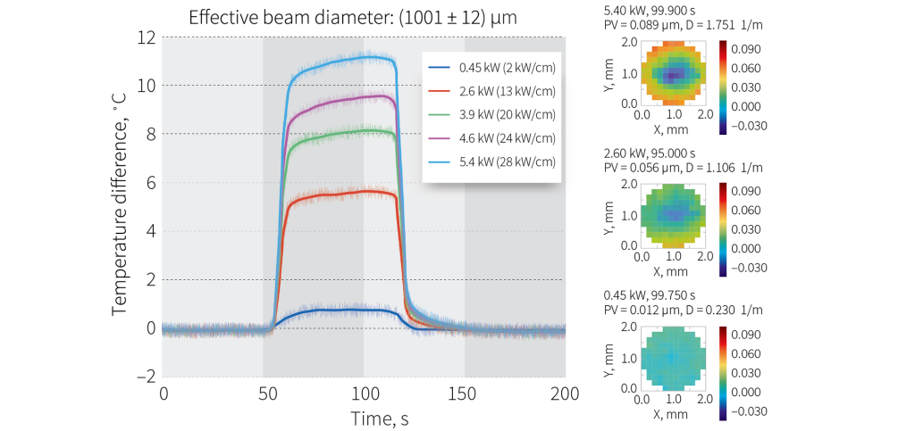
Figure 1. Demonstration of wavefront distortion and thermal lens formation on the laser-irradiated area of an optical component that shows the average absorption of 10 ppm.
Components for systems with a demanding beam stability
As has already been suggested, the thermal lens formation and the focal shift could be a concern for applications with a demanding laser beam stability, where only low-absorbing flat surface optics can provide the best quality.
Altechna can provide different solutions for your demanding beam stability applications with regard to your requirements, by offering a variety of optics with a low thermal response and high beam stability within an acceptable pricing range.
Specifications:
- Wavelength: 1070 nm
- HR Coatings: R >99.9%
- Absorption (p-pol): 1.5 ppm
- Temperature rise at 6 kW: 0.45˚C
- LIDT T-on-1: >408 kW/cm
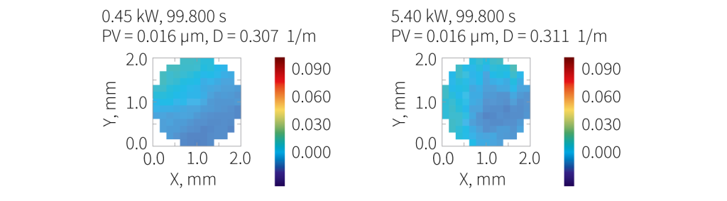
Figure 2. Thermal lens formation and wavefront distortion on High ReflectivityMirror HR (Ravg>99.9%) @ 1070 nm, AOI=45°.
Specifications:
- Wavelength: 1070 nm
- AR Coatings: R <0.5%
- Absorption: 0.5 ppm
- Temperature rise at 6 kW: 0.3˚C
- LIDT T-on-1: >295 kW/cm
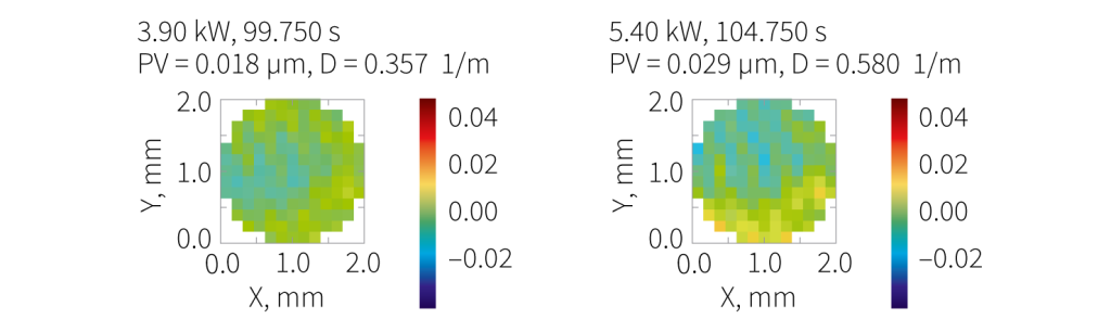
Figure 3. Thermal lens formation and wavefront distortion on High TransmissionOptics AR (R<0.5%) @ 1070 nm, AOI=45°.
Specifications:
- Wavelength: 1064-1080 nm
- AR Coatings: R <0.1%
- Absorption: <0.3 ppm
- Temperature rise at 6 kW: <0.1˚C (below the system detection threshold)
- LIDT T-on-1: >428 kW/cm
Figure 4. Transverse scan by PCI. Absorption of the high transmission optics solution AR (R<0.1%) @ 1064-1080 nm, AOI=0°.
Components for high-power narrow laser beam applications
Because the gain medium in fiber lasers is exceedingly thin and flexible, optical fibers may be kilometers long, and therefore achieve a very high gain in the pumping light. As a result, fiber lasers may operate continuous at powers in the kilowatts.
Furthermore, a narrower beam width allows for the manufacturing of finer structures in the materials processing field, as well as the employment of smaller and less expensive optical components. However, making the system smaller means that it needs to be more resistant to laser damage.
In general, the LIDT of the optical components used at CW laser wavelengths are defined by the melting temperature of the compound materials. However, ideal substrates and coating materials, which would have a well-ordered, homogeneous, and chemically stoichiometric structure, do not exist in real-world conditions.
Therefore, a CW laser system will only be as strong as the weakest part of the system–its defects and their density in the optical components. Hence, localized defects will determine the final performance of the coating. In high-quality optics, the number of random defects can be reduced to the minimum by advanced process optimization. [1]
In less demanding laser beam quality applications, Altechna offers more cost-effective and higher throughput manufacturing solutions, for easy and efficient large-scale orders with optimal CW performance capabilities, as can be seen in Figure 5.
Specifications:
- Wavelength: 1070 nm
- AR Coatings: R <0.1%
- Absorption: <1.4 ppm
- Temperature rise at 6 kW: 0.7 ˚C
- LIDT T-on-1: >191 kW/cm
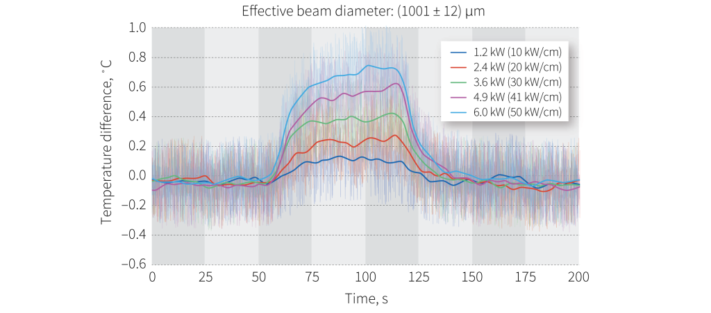
Figure 5 (a, b). Cost-effective option of a high transmission CW optics component for laser systems with less demanding CW requirements. Optimized for lasers with a 0.3-4 mm effective beam diameter and up to 6 kW power.
Components for high-power laser scanning or wide beam applications
Finding the proper optics becomes even more difficult when the laser beam needs to be scanned through the optics surface or when larger beam diameters above 4 mm are employed.
This is because of the random defects, which at high-quality optics typically appear in very low densities and, in general, are not that harmful in the cases previously described.
The optical component manufacturing processes can induce scratches and digs, while polishing is associated with the formation of the Beilby layer. Nodules can also appear during the coating process.
These randomly distributed defects can increase localized absorptance, which makes them dangerous, especially for CW or other long laser pulses. The conventional approach to LIDT testing, which involves testing a matrix of multiple isolated dots (T-on-1), is not suitable for all applications [4].
In these instances, a raster scan is required. When exposed to a narrow laser beam, considering the size of the component, the chances of hitting these defects are low. This is particularly true when the defect density has been reduced within the manufacturing process already.
However, while using a narrow beam in LIDT testing, the raster scanning procedure, schematically described in Figure 7, is the only way to determine the suitability of the components for materials processing, additive manufacturing or even mining industry applications, where a large area of the optics surface needs to be irradiated.
For example, as is suggested by Figure 6, high surface quality optics LIDT tested in the Raster scanning mode can reach linear power density levels above 428 kW/cm.
Specifications:
- Wavelength: 1070 nm
- AR Coatings: R <0.1%
- Absorption: <0.3 ppm
- Temperature rise at 6 kW: <0.1˚C (below the system detection threshold)
- LIDT Raster scan per 1 cm2: >428 kW/cm
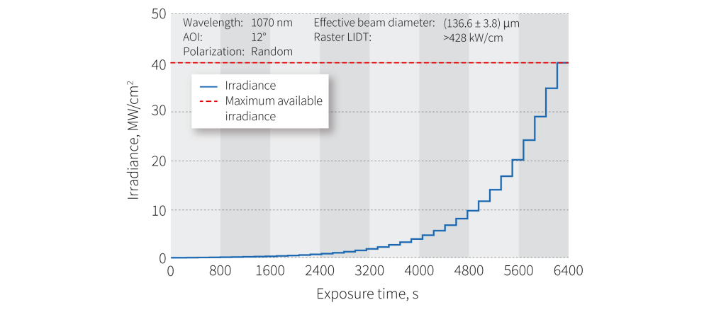
Figure 6. Raster LIDT of High Transmission Optics AR (R<0.1% @ 1080 nm, AOI=0°).
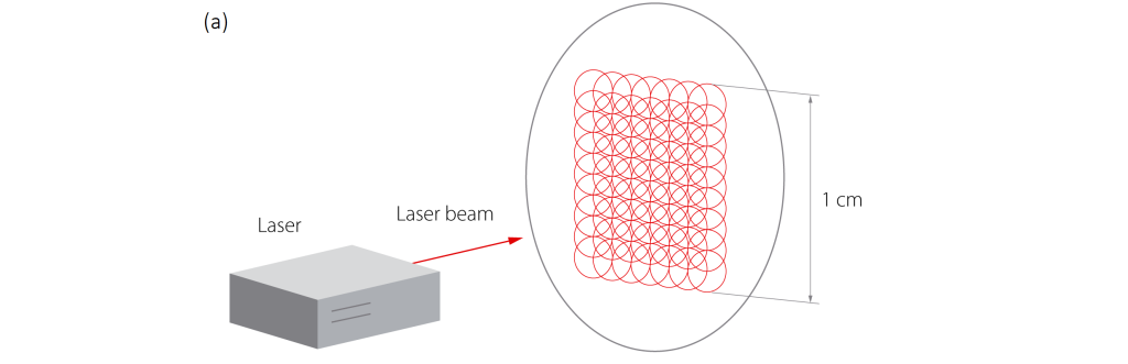
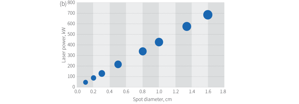
Figure 7. a) Raster scan LIDT testing procedure [5],b) Relationship between CW laser power resistance and spot size.
All of the optical components at Altechna are characterized based on the procedures that are the most up-to-date and the most relevant to the application. Therefore, all our components suitable for high-power CW laser scanning or wide beam applications are tested in the Raster scanning mode, to ensure a high LIDT and quality repeatability.
Due to the novel surface quality developments and the strict process controls at Altechna, our optical components working in wide beam applications can withstand the laser powers provided in the specifications.
Order today
Altechna offers solutions for most optical components used in demanding CW and quasi-CW laser systems (windows, lenses, prisms, etc.).Feel free to contact our professional team to receive our best support services: [email protected]
References
1. K. E. Puttick, R. Holm, D. Ristau, U. Natzschka, G. Kiriakidis, N. Garawal, E. Judd, D. Holland, D. Greening, N. Ellis, M. Wilkinson, M. G. Pamies, C. Sanviti, “Continuous-wave CO2– laser-induced damage thresholds in optical components,” Proc. SPIE 3244, Laser-Induced Damage in Optical Materials: 1997, (April 20, 1998); https://doi.org/10.1117/12.307045
2. M. Gželka, “Transmissive Optical Components for >100 kW CW Laser Systems,” Altechna (https://www.altechna.com/whitepapers/transmissive-optical-components-for-100-kw-cw-laser-systems/) (October 4, 2020)
3. R. A. Negres, C. J. Stolz, S. B. DeFrances, D. M. Bernot, J. A. Randi, J. G. Thomas, “1077-nm, CW mirror thin film damage competition,” Proc. SPIE 12300, Laser-Induced Damage in Optical Materials 2022, 1230002 (December 2, 2022); https://doi.org/10.1117/12.2641371
4. ISO 21254-2:2011: “Lasers and laser-related equipment -Test methods for laser-induced damage threshold – Part 2: Threshold determination”, International Organization for Standardization, Geneva, Switzerland (2011)
5. https://lidaris.com/tests/raster-scan-lidt-test/ (June 6, 2023)